Saturday, April 24, 2010

Final Challenge-9

For the last part of this challenge, we combined everything that we learned into one program. Our goal was to make the MotorCar move straight for 10 feet up the ramp. In doing so, we used our straight-proportional program and our nudge program. So we combined these programs together and basically looks the same as our previous program from challenge 8. However, this time when we tested our MotorCar on the ramp, it didn't move straight. It was very strange because in our previous programs, it had successfully moved up the ramp without falling off numerous times. So we decided to take a closer look at our straight-proportional program. We saw that there were a few problems in our program. We first created a "protect" block that would ensure that the power settings would remain withing the range of 0 and 10000. Before, we did not have a way to limit the setpowers and if our they were set to numbers that were negative or higher than the full power, it might have caused our proportional program not to work properly. The second thing that we did was to change the equation that determined our proportional control. We did not know that LogoChip did not consider order operations. It reads an equation from left to right. Therefore, LogoChip misinterpreted our equation to be (10000-count-)*800. While this is what we intended our equation to be: 10000-(count-*800). So we altered the order of our equation. This is a picture showing the changes that we made:

This is our program for the protect block:

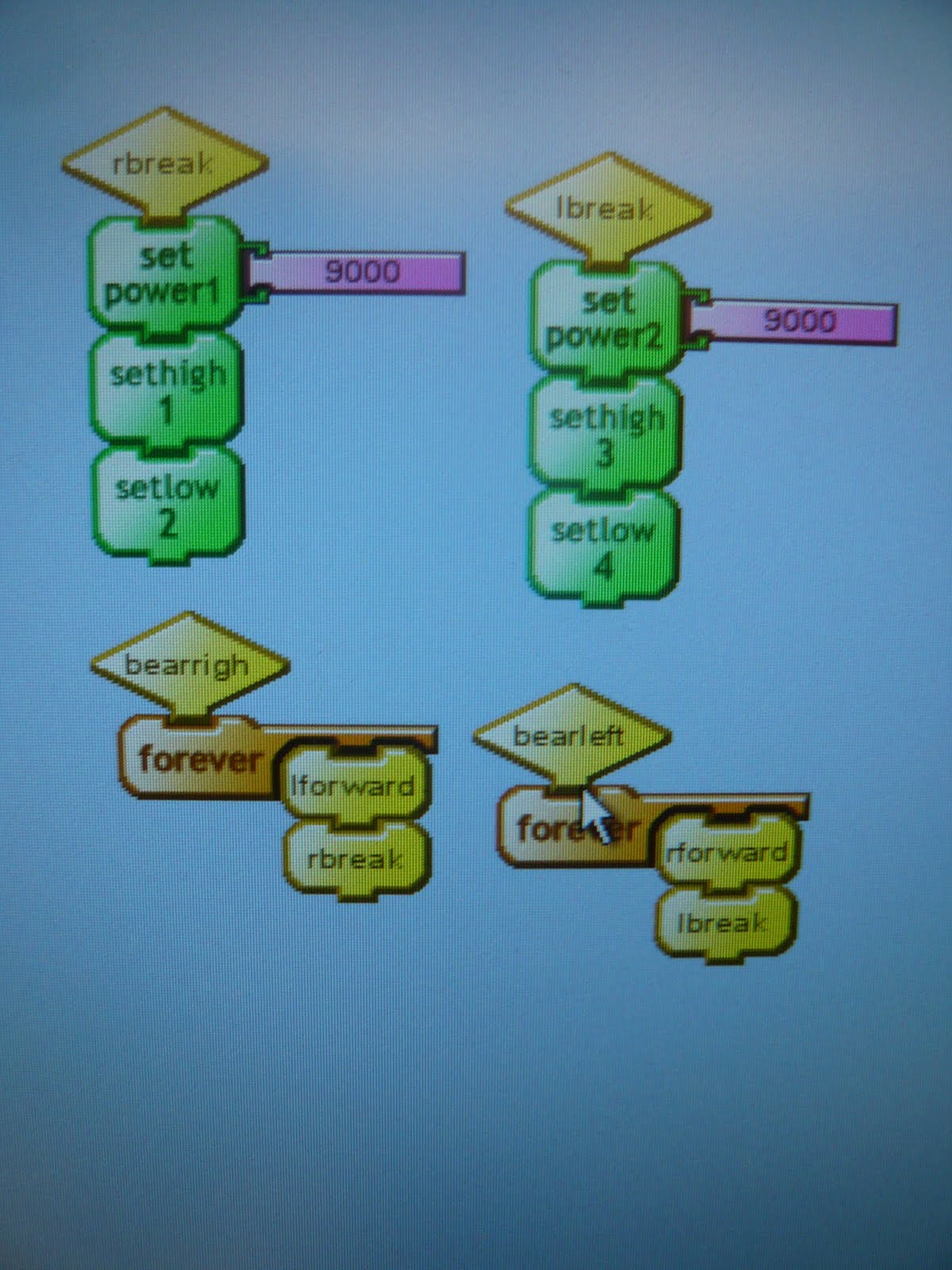
These are the blocks that determine proportional control:
These are our nudge and straight-proportional blocks:
and we combined them to create a program to make the car go exactly ten feet:


After making those changes, we tested our program and this time the MotorCar wobbled and still beared to the right. To decrease the wobbling we decreased our gain from 800 to 200. But even after changing the gain, the car still beared to the right. So then we decided that the problem was in the wheels. To test that out, we switched the two wheels and tested our program again. The problem did lie in the wheels because the car, this time, beared left. There must have been a slight difference in the diameter of the wheels which would have completely thrown off the counts and made our proportional program ineffective. So we tested out different wheels until we found a pair that would make the MotorCar move the straightest.

This is a video of our MotorCar moving up the ramp. The car moved fairly straight but we had to nudge it a little bit so that it wouldn't fall off. We were disappointed that we had to do this because in previous challenges, our car was able to move along the ramp without falling. However, the car stopped really close to the 10 feet target.


This is a video of our MotorCar moving down the ramp. Like when going up the ramp, we had to slightly nudge our MotorCar. The car did, however, stop fairly close to the 10 feet target.


The last two videos are of the MotorCar on the concrete floor and on the carpet, respectively. On both of these surfaces, the car beared to the right. On the carpet, it beared greatly to the right. These tests were one of the worst out of all our LogoChip challenges. We didn't really understand why this happened because our programs were working fine before. So one of the reasons that our final programs didn't work as well was that the wheels were changed, which would have messed up our counts because the wheels are not exactly the same. Unfortunately, we didn't have much time to invest in fixing this problem because Esther and I had to concentrate on the final project. However, we will certainly use our straight proportional program in our final project because our robot would have to move straight for 10ft to reach the candle.


Saturday, April 17, 2010

Final Challenge-8

For this part of the challenge, we created a "nudge" procedure that caused the car to move a very small distance for a brief moment. Because with proportional control, the car can overshoot or undershoot its target, so we used nudging to make the movement of the car more accurate. We used this program to make the MotorCar repeatedly move up or back up towards the target. This procedure would help us make the MotorCar get closer to the target of 10 feet up the ramp. This is a picture of our nudge program:


This is a picture of our nudge program: Our nudge program consists of backing up and moving forward at a lower power. If the count was higher than a certain count then the car would back up and if the count was lower than a certain count then the car would move up. We then added a last part that would make the car coast once the car was at a certain range of the count. After completing the "nudge" procedure, we combined it with our " straight proportional control" procedure.

Our "straight proportional control" was a set to stop the car at a certain count. Our count was 3050 and it made the car move exactly ten feet on the concrete floor. This is a picture of this procedure:


We then combined these programs with an "init" block that would start the count and "forward" blocks that would start moving the MotorCar. This is a picture of our final program:
So we tested it out on the ramp and the car did not reach the 10 feet mark but it came up very close. This is a picture that shows how close the car came to the target:
One of the reasons we think that the car make the 10 feet mark was that it slipped on its way up the ramp. The skidding would create problems with the counts, making it miss the 10 feet mark. So we decided to lower the incline which would reduce the slippage. This is a picture of how far we moved the ramp down:
So we retested our procedure and we found that the car moved a lot closet to the 10 feet mark. This means that the more the ramp was level with the ground, the more the car would reach the target.
We then tested our procedure in different situations. We had the car go downhill and like previous tests, it went past the 10 feet mark. In this situation, the car slipped, making the car overshoot the target. This is how far the car passed the target:
We then tested it out on the carpet. And unlike our previous tests, the car made the 10 feet mark exactly. Here is a picture of the car after the procedure was done:
This is a video of the car moving on the concrete floor and nudging towards the 10 feet mark:

Thursday, April 15, 2010

Final Challenge-7

For this challenge, we created a procedure that uses proportional control to make our car go exactly ten feet. Like the previous challenge, we combined two of our older programs "go ten feet" and "proportional control". However, instead of using time to control when the motors were running, we used the counts with the use of shaft encoders. We used our unit of .037 inch/count to figure out how many counts where needed to go a distance of 1o feet. We obtained a total count of 3243 and we tested it out to see it worked, but the car passed the 10 feet mark. So we lowered the count to 2960. So this is the program we came up with:

Like in the previous challenge, we made the car coast instead of braking. Below is a picture of our power settings and how they are a product of a constant gain factor and the average of the shaft-encoder variables.
After making our program, we tested it out on the concrete floor. It worked extremely well (moved very straight) and stopped exactly where it was supposed to.
Here is a video of it:


We then tried it on the carpet. The MotorCar beared right slightly, not as badly as it did when it was running under the "bang bang distance" program. This time, the car stopped short by 2 inches of the 10 feet mark.
Here is a video of it:


We then tested our program with the car going up the ramp. We were impressed because the car moved very straight and it came closer to the mark then when it was running the "Bang Bang" distance. It was about 4 inches short of the 10 feet mark.


Finally, we tested it out with the car going down the ramp. The car beared to the right but it straightened out very well, which made us very happy and convinced us that our proportional control was working. The car did not pass the 10 feet mark as much as it did the "Bang Bang" distance control. Instead of being off by a foot, it was off by around 6 inches. Here is a video of it:

These trials showed us that the proportional control worked much better than the bang bang control for this distance challenge. But we were still unable to make the car stop exactly at the 10 feet mark on the three surfaces (upramp, downramp, carpet).

We then tested out different gains because we wanted to see how it affected the motion of the MotorCar on the concrete floor. Our original gain was 800. We first tried a lower gain of 100. This resulted in the car deviating right. It still went 10 feet, but it did not go straight at all. We then tried a higher gain of 1300. The car still went 10 feet but it also deviated to the right. This showed us that we had the right gain and that changing it would really affect the results and if we had tested it out the ramp, the car would have surely fallen off.


Final Challenge-6

For this part of the challenge, Esther and I wrote a procedure that used bang-bang control to make our car go exactly 10 feet. We also had to stop the motors only by coasting, not by braking. In order to achieve this, we combined our "go ten feet" and "bang bang control" programs into one. We used time to tell when the motor needed to coast. The time we used for our program was lower than the one we used for the "go ten feet" procedure, because we had to take into the account the extra time it took for the motor to stop, since it was coasting.
This is a picture of our program:

We then tested out our procedure on different surfaces. We first tried it on the concrete floor and it worked very well. The car fairly straight and it stopped exactly at the 10feet mark.
Here is a video of this:

We then tested it with the car going up the ramp. The car beared slightly left but it did not fall off. It was short of the 10 feet mark by around 8 inches. Here is a video of this:


We then tested it with the car going down the ramp. The car almost fell off as it beared right, but managed to straighten out very nicely. The car passed the 10 feet mark by almost a foot. Here is a video of this:


Our final surface was the carpet. We measured out ten feet on the carpet. This was the least successful trial because the car beared left very noticeably and it missed the 10 feet mark by 3 inches. Here is a video of this:


Sunday, April 11, 2010

Final Challenge-5

For this part of the challenge, we wrote a procedure that would make our car travel approximately 2 feet, then reverse and return to where it started from. For this challenge, we copied the program for the previous challenge. Since we know that the distance per count is about the same for the left and right wheel, we were able to find how many counts was needed to travel 2 feet. We multiplied 2 feet by 12 to get 24 inches and then divided that amount by .037 inches/count to get a value of 648 counts. We first tested that value on the program that we created earlier and the car did in fact travel 2 feet.
In order to create this procedure, we made two programs (one for the forward directionand the other for the reverse direction). This a picture of these two programs, entitled "2ftfor" and "2ftback":
We then combined them under our "bandf" program (back and forth). We remembered to add a wait of .2 seconds in between the two directions. We also remembered to put a "stopstack" block at the end of both our programs so that they would hand over the control.
This is a picture of our final program:


This is a video of our "bandf" program.

We saw that when the car reversed and went towards its original location, it didn't quite make it. It about an inch to go before it attained its original starting position. To fix that, we can alter the count on our"2ftback" program.
We then test our program with the car starting uphill on the ramp. As the car moved up, it didn't make reach the 2 feet mark. As the car reversed, it went passed its original location by a couple of inches.
When we started the car going downhill, the car passed the 2 feet mark and as it tried to reverse, its skidded for a couple of seconds and proceeded to travel back up, but it did not reach its original location.

After that, we created a program that would repeat this process 3 times. This is what our program looked like:

We first tried it on the concrete floor. The car ended ip being much further from the starting line ( by a couple of inches). When we tried it on the ramp, with the car first travelling up, the car went further back from the starting line by a couple of inches.

Final Challenge-4

For this part of the challenge, we developed a procedure that that made our MotorCar go exactly 10 feet. We used a timer to control the amount of time the motor would be on for. . In order to figure out this time we timed how long it took for our car to move 10 feet on the concrete floor. The times that we obtain were not very consistent because the MotorCar did not travel in a perfect straight line. However, we were not worried about the vehicle moving straight at this point. So our average time was around 8.86 seconds and we incorporated it into our program. In PicoBlocks 1 seconds corresponds to 1000, so 8.86 seconds would be 8860. We first tried out our program with the motor stopping after the times exceeded 8.86 seconds and the MotorCar passed the 10 feet mark by an inch. So we decided to lower the time to 8.5 seconds. When tried it on our MotorCar, the car stopped exactly at the line!
Here is our program on PicoBlocks:

And here is a video of our MotorCar travelling 10 feet:


After making sure that our program worked on the concrete floor we tried it in different situations. When we tried it with the car going uphill, it stopped short of the 10 feet mark by a foot. When we tried it with the car going downhill, it passed the 10 feet mark by 3/4 of a foot. The fact that the car is travelling downhill or uphill definitely matters because the car moves slower as it travels up and moves faster as it travels down the ramp.
We then replaced our "stop" block with a "coast" block to see the difference between the distances that the car would travel. In fact, when the car coasted at the end of 8.5 seconds, it passed the 10 feet mark by a couple of inches.

We then, using the shaft encoders, measured how many "counts" it took for the car to travel that distance. We created a program that printed "count a " and "count b" for 8.5 seconds.
"count a" was 3237 and "count b" was 3225. All of these measurements were taken on the flat concrete floor.
This is a picture of the program that allowed us to obtain the counts:

We then figured out how far was one "count". We divided 10 feet with the counts that we obtained and the result was that for both "count a" and "count b", the car moves .037 inches per count.
If the car were to skid, which means that the car would move but the wheels would not spin, the distance per count would increase.
If the car were to slip, which means that the car would not move but the wheels would still spin, the distance per count would decrease.

Final Challenge-3

For this part of the challenge, Esther and I created a program that uses proportional control to make the MotorCar go straighter. In order to do this we changed our previous Bang-Bang control program. Instead of the "set power" blocks to be fixed to a certain value, we made them vary according to the count difference. When the count was positive, we subtracted the difference times a gain (a coefficient) with the total power (10000). When the count negative, we added the count difference times the gain to the full power. This means that if the count difference is small then the set power will be set to a value closer to full power, which would make the vehicle only bear slightly left/right. If the count difference is great then the set power will be set to a value much smaller than full power, which would make the vehicle bear left/right much more. We had to figure out what gain we needed to incorporate in our program. After a couple trial and error runs, we found that the gain value of 800 was the correct one and made the MotorCar move very straight. This is a picture showing our "set power"blocks:This is a picture of our "straight porprotional" program. Except for the "set power" blocks, it looks exactly the same as the Bang-Bang control program.
We first tested our program on the concrete floor along the tape line. The MotorCar stayed within the line, but it beared to the right slighty. This is a video of it:

We then tested our program up on the ramp. The MotorCar successfully managed to reach the top without falling. This is a video of it:

Then we tested our program down the ramp. The MotorCar beared to the left and was very close to falling off. This is a video of it:

Then we tested our program on the carpet. The MotorCar didn't move as straight on this surface compared to the other ones. But it did not deviate too drastically. This is a video of it:

After testing our program on different surfaces, we tested by altering the friction on the wheels. When both wheels had low friction, the MotorCar moved fairly straight and beared slightly to the right. When one wheel (left wheel) had high friction, the MotorCar moved just like when both wheels had low friction. Finally, we set both wheels to have high friction and the MotorCar moved very straight! It followed the tape line perfectly!

Then we tested to see how changing the gain would affect the MotorCar's straightness. When we set the gain to be 50, the MotorCar drastically turned towards the right. When we set the gain to be 500, the vehicle wobbled a bit and beared to the right. Then we set the gain to be 1110 and 1550, the MotorCar beared to the right but not as noticeably as when the gain was set to a much lower number. We finally tried 900 and 700 and the MotoCar moved fairly straight but beared slightly to the right. After testing all these different values, we re-tried our program with the value of 800. The MotorCar moved very straight and it showed us that we were able to constantly reproduce a straight path when our gain was set to that value.

Friday, April 9, 2010

Final Challenge-2

For this challenge, Esther and I used Bang Bang control to make our MotorCar to move straighter. In class, Professor Berg showed us a visual example of Bang Bang control with a sensor, a candle, and a fan. The sensor was placed above the candle. In his program, he wanted the temperature to stay constant so when the sensor sensed that the temperature was a above a certain point, then the fan would start. When the temperature was a below a certain point, the fan would stop. The graph for the program oscillated and that is a characteristic of Bang Bang control.

We used the count difference (count b- count a) to determine whether the Motorcar should bear left or bear right and thereby constantly adjusting itself to move in straight line. We saw that when the count was positive, the Motocar drifted towards the right and we needed to add friction to the left wheel so that it would bear left. When the count was positive, the Motorcar drifted to the left and we needed to add friction to the right wheel so that it would bear right.
So we created a program "s-bb" that used the "if then else" blocks and the "bear left" and "bear right" blocks that we made in the previous challenge.
We added a print statement so that we could see the count difference and we could also see the oscillation because the count would vary from -3 to 3.
This is our program:
We had some difficulties writing this program because some of the blocks that we used, such as the "forward", "bear left", and "bear right" blocks, had forever loops in them. Since the forever loops never give up control, the program that we had written up above never worked. When we ran the program, the Motorcar would just move forward forever. So this was one of our major problems. We had another problem that made things a little bit confusing. We had our left wheel associated with count b and our right wheel associated with count a. We should have had it the other way, so in order to correct this we just switched the wires so that the right wheel would be connected to inputs 1 and 2 and the left wheel would be connected to inputs 3 and 4. By having these mixed up, we were not able to correctly use the count difference and had the wrong notion of what happened when the count difference was negative and positive. However, when we took away the forever loops and connected the wheels to the right inputs, our program worked really well.
We played around with the power settings hidden in the "bear left" and "bear right" blocks. We had previously had the power settings reduced to 9000 and when we ran the program, we could see a minor wobble in the Motorcar, hence the oscillation. So we decided to make the difference slightly smaller by have the the power settings reduced to 9700. When we ran that program, the Motorcar did not wobble and moved straight!

So we tried our program on different surfaces.

We first tried it on up on the ramp. Here is a quick video of it:


Then we tried it down on the ramp. We found that the MotorCar moved a lot straighter while it was going down the ramp and than up the ramp. As it was going up the ramp, it beared right a little bit and wasn't able to make it all the way to the top. However, the MotorCar was able to make it all the way down the ramp without falling off.
Here is a video of it:


When then just tried our program on the concrete floor along a tape line. Here is a video of it:

When we set our MotorCar on the carpet, it did not go as straight as it did on the concrete floor.
Here is a video of it:

We then tested out program under different conditions. We first set both wheels to have low friction. The result was that the MotorCar went fairly straight on the tape line but it beared right slightly in the end. Then we gave one wheel (the right wheel) higher friction and the result was that the MotoCar wobbled a lot more than before and this time it beared slightly to the left. Finally, we set both wheels to have a higher friction. This time the MotorCar moved the straightest along the tape line , even if was a bit wobbly.


Final Challenge- 1

For this part of the challenge, Esther and I were introduced to the problem of making the MotorCar move straight. In the previous challenge, we made a program that would move the MotorCar forward, but it did not necessarily make it move straight. When we observed the Motocar go forward, we saw that it beared slightly to the right. In order to test the straightness, we used a tape line on the floor as a reference point and the ramp set up in the classroom.
Because our MotorCar beared to the right, we decided to add friction to the left wheel by pushing it inwards towards the motor. The result was that the MotorCar now beared towards the left. We had made too great of an adjustment.
When we added friction on both wheels, the MotorCar did not move straight at all. It looked like it was spinning to the right.

It was hard to find the right position of the wheels on the axle for the MotorCar to move straight.

Tuesday, April 6, 2010

challenge #8- 8.3

For this challenge, Esther and I used shaft encoders to program our MotorCar to go forward until "counta" is 1000 and then go backward until "counta" is 0.

We first copied a code on the course website into the Procedures Window as text-language on PicoBlocks. This code created new blocks that allowed us to count in a separate thread and to watch the shaft encoders that control the two motors.

Like in Challenge #6, we went about making this program in two parts. We created two separate threads: one that tells the motor to go forward for a certain count and the other tells the motor to go backward for a certain count. We set that once counta was higher than 1000 (in the first part) or once counta was lower than 0 (for the second part), the motors would stop.
This is a picture of these two threads:

We then combined these two threads to create our program. We added a wait block because quickly reversing the motors can generate power spikes that cause the LogoChip to crash.
This is a picture of our program:
Here is a video of our program:

challenge #8- 8.2

For this challenge, Esther and I constructed simple PicoBlock procedures to make the motor move forward, backward, coast, brake, spin right, spin left, bear right, and bear left.

Before we even started making these programs, we had problems with the wire that hooked up the LogoChip with the computer. The PicoChip program kept indicating that the there was a "Communication Problem". In order to find the exact problem, we had to do a little of debugging and we were able to find that a wire was not properly connected to its pin. Therefore, we had to re-sauter the wires unto new pins.

After fixing that problem, we were able to make our programs. This a picture of our programs that control each side of the motor. There are forwards and backwards blocks that control the right and left side of the motor.
We then combined these blocks to make the robot move forward, backwards, stop, coast and to spin on either side. This is a picture of these programs that produce these motions:
We then made two programs that would make the motor break left and right. In order to do this, we had to set a motor to a lower power, so that the robot would drift towards the side where the motor is fastest. This is a picture of these programs:


Monday, April 5, 2010

challenge #8- 8.1

For this part of the challenge, we built a MotorCar out of legos that is propelled by two NXT motors. We followed the step-by-step guide in the Lego Manual Kit and on Extd160 website. This was a fun process and it was interesting to see this vehicle come all together.

This is a picture of our MotorCar after following the step-by-step guides:

We then had to connect the second motor to the LogoChip. In doing so, we had to solder up a wire with pins so that it could connect to the breadboard. I had previous experience with soldering, so now this was a pretty easy process for me.
This is what we came up with:

We then had to connect the second motor in a way analogous to the first motor cable. This was a bit confusing with all the wires, but by following the pin diagram on the website we were able to connect everything pretty easily.
This is what our final product looked like:


We also connected the motors to the p1 and p2 outputs on the LogoChip so that we would be able to control them independently and control the power delivered to each motor. All we would have to do is use the setpower blocks on PicoBlocks to control the power of these motors.


Saturday, April 3, 2010

Challenge #7- 7.3

For this part of the challenge, we connected a H-Bridge with our LogoChip. The H-Bridge controls which way the current flows, which would make the wheels of the motor turn in both direction. It always allows to hook up the motor to a higher voltage. We connected a pin on the H-Bridge to another battery pack. We also connected the inputs on the motor driver to the two outputs on the LogoChip. We used a schematic drawing to properly connect the motor driver with the shaft encoder and the LogoChip.

After connecting everything, we tested out various procedures on the motor. In order for the motor to turn a certain way, we had to set one output to high and the other to low, and in the reverse order for the motor to turn the opposite way. However, this did not work. Esther and I were confused because we didn't know what those simple procedure didn't make the motor move. We double checked our breadboard and everything was at its right place. We then figured out that we had to set output 3 (which is connected to the enable pin on the motor driver) to high. After figuring that out, we were able to make the motor go in both direction, stop, and coast.
These are the programs that make the motor perform this procedures:

Then we had to construct a program that uses feedback from the shaft encoders to make the motors spin exactly 10 revolutions one way, stop, and spin back to exactly where it was.

We first to find a "unit conversion" for how many clicks were in one revolution. So we used our previous "counter" program from challenge 6 and we found that there were 180 clicks in 1 revolution- 1800 clicks in 10 revolutions. However, a problem arose when we saw that the number of clicks in one revolution differed when the motor was running (because previously we manually turned the motor) and when the motor turned in the opposite way. This was very problematic, but we ended up adjusting ourselves the number of clicks that the program needed to count both clockwise and counterclockwise.

When making this program, we split up the first part (moving that way) and the second part (moving the other way). In each part, we included the "counter" program that we created in challenge 6. For the first part, we told the program that once the number of clicks had surpassed1038, the program should stop. For the second part, we told the program that once the number of clicks had gone passed -855, the program should stop.
These are the two programs:

We then combined these two programs and put a wait in between them, so that the stop would be more pronounced.
This program took us a lot of time to figure out because we had to both count the clicks and tell the motor for a certain amount of time all in the same program. This is why we split the two motion, because we wouldn't be able to perform all this procedures in a single thread.

This is a video of us performing the simple procedures:


Challenge #7- 7.2

For this part of the challenge, we had to create a program that would take in account the "net" count, counting up as the motor rotates one way and counting down as the motor rotates the other way. In order to do this, we used the oscilloscope to see if there was a difference in the signals as we turned the motor in one way and in the other. We used the channel 2 to detect the edges of S2. Channel 1 was yellow and Channel 2 was blue. As we turned the motor clockwise, the yellow signal appeared first, indicating that the edge 1 came before edge 2. As we turned the motor counter-clockwise, the blue signal appeared first, indicating that edge 2 came before edge 1. This is a picture of what we saw on the oscilloscope:


We noticed that when the motor was rotating clockwise, edge 1 came first and edge 2 was still present. While when the motor was rotating counterclockwise, edge 2 came first and when edge 1 appeared, edge 2 was no longer there. We used this information in our program to get a sense of the motion of the motor. We created a forever loop that detected these different edges. We first checked the state of the first sensor (detect the edge 1) and then checked the state of sensor 2. If the program detected sensor 2 then this meant that the motor was rotating clockwise and if the program didn't detect sensor 2, the motor was rotating counterclockwise. The oscilloscope was extremely helpful in distinguishing these two motions and helped us come up with a pretty clever program.

This is the program that we came up with:
We made the program so that if sensor 2 was detected (motor going clockwise), the count would go up and if sensor 2 was not detected (motor going counterclockwise), the count would go down.

Challenge #7- 7.1

For this challenge, we were introduced to shaft encoders which are built in the NXT motors. They allow you to sense how much the motor's "shaft" has rotated.

We first connected the shaft encoder on our breadboard, connecting S1 and S2 the inputs 1 and 2 respectively on the LogoChip. We then used the oscilloscope to monitor the shaft encoder. As we turned the NXT motor, we were able to see the edges of S1 on channel 1 of the oscilloscope.

We then had to write a program that counts and prints the edges of S1 as we turned the motor by hand.
This was a relatively simple program because we didn't have to take in account switch bounces and the direction that we turned the motor in, therefore the count always increased.

challenge #6

For this challenge, we had to create a program that can detect multiple edges in a single thread. This means that we had two switches connected to two separate lights, which we wanted to toggle every time we pressed the corresponding switch . At first, we thought this would be an easy program to construct. We thought that by just putting "waituntil" and "waituntil not" in our program to detect rising edges, the switches would toggle the lights. This worked, but only if you followed the order that the switches were placed on the program. We weren't able to choose which light we wanted to toggle at any given point because if we didn't follow the order on our program, the thread would just get stuck. This was very problematic, so we decided to find solution. Wemake two separate programs for each switch but we wouldn't be able to run these two programs simultaneously without using the "wand" tool on PicoBlocks. The "wand" tool allows for two different threads to run simultaneously. However, the "wand" tool allows to run only two programs that the same time. So we had to find a another solution that would work for however many programs.

In order to do this, we used the text language in PicoBlocks to create variables and conditionals without grabbing control.


With Professor Turbak, we used the text language to create variables and four new blocks (block edge 1, block edge 2, block test-edge 1, block test-edge 2), which can you see in the picture above. The block edge 1 and 2 detect if the switches have been pressed by checking the previous and current states. If the program sees that the previous state and current states are different, it indicates an edge and it toggles. The block test edge 1and 2 detect these edges in a forever loop and waits for switch bounces. When pressing the block test-edge1 and block test-edge 2 blocks, they each toggled a light.
Now that we saw the format on the text language, we combined these two actions into one block (block test-edge 12) This is the program that we came up with:


The program looks relatively simple, but it took us a bit of time to decipher the text language and to understand exactly what was going on.

This is a video of our program in use:

.