We needed an extra battery pack and we had to solder on headers so we could connect it to the Logochip. This was the second time I had soldered and it was great practice to solder the header on the battery pack.
Esther and I had to carefully wire in the transistor and the extra battery pack into the breadboard because if we did it incorrectly we could fry our Logochip. This was a pretty tedious process because we had to make sure all the wires were connected to the right three pins in the transistor and on Logochip.
We used the setpower command on PicoBlocks to control the power of the Motor and we were able to give the motor more power. We than created a program that slowly ramped up the motor up to its maximum speed and slowly back to zero.
This is what the program looked like:
 To create this program we used the Introduction Packet on Logochips to help us. In the Introduction Packet, there were directions to make a light brigther and dimmer. We adjusted this program by figuring how many times we needed to repeat the program in order for the motor to reach its maximum power and its lowest power. We first created two blocks: one that would make the motor go faster and the other go slower. Then we combined the two blocks and that was our program.
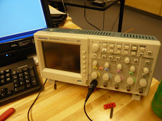
We were also able to hook up the LogoChip with the oscilloscope and we could see the pulse of the motor and how the wavelengths shortened as the motor ramped up.
This is an image of the oscilloscope:
 This is a video of motor running under our program:
 This is a video of motor running under our program:
No comments:
Post a Comment